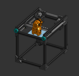
Current State
This is the current state of the printer.
Build Process
Initial Idea
I initially thought of this idea after buying a 3D printer, and wanting to be able to customise and fine tune my printer better. I was heavily inspired by Voron Design, who designs open source 3d printers and publishes build manuals. While I could have just built a Voron, building my own design from scratch seemed like a good way to hone my skills for my projects.
There were many initial decisions I had to make, such as the main motion system of the printer, the build volume, and the main usage purpose of the printer. I decided to build a printer that would let me rapidly iterate my designs, which are often small. I chose to make a corexy printer, as they are generally faster and have a smaller footprint than the main alternatives. As the large majority of my prints are very small (less than 80mm), I decided to use a small build volume, which also keeps the footprint and costs down (My budget is quite limited as a student).
However, I also decided on other purpose of the design: to not just print in 3d, but also be able to use pens to pen-plot, and potentially also cutting tools. Many people have adapted their prints into cutter-plotters, but this often sacrafices the printer. The goal will be to easily swap between plotting, cutting and printing with minimal effort.
Market Research
I looked at some 3D printers such as the Voron Zero, Voron Trident, Bambu Lab P1S, and Bambu Lab H2D.
The Voron Zero uses a good motion system, but has a cantilevered bed, which likey wouldnt work in my inital designs due to the extra axis space required for plotting and cutting. The Voron Trident uses a triple leadscrew method, alongside the P1S. The P1S however uses a belted Z axis and one motor, which saves on cost at the expense of bed tramming. As bed tramming is not required at the small bed scale I am working at, a belted triple leadscrew looks effective.
The H2D seems to be the only printer on the market that also has cutting and plotting capabilities, but they seem quite limited. The H2D does not seem to work too well with more precise plotting using fineliners, and instead only uses felt tips. The H2D does have quick swapping however, which keeps downtime low when switching processes.
Rough Initial CAD Design
Here is my first inital CAD design. This version has a relitively fleshed out XY Axis, with stepper motor mounts and linear rails, but has only a very basic frame.
I decided to use 15mm aluminium extrusion (Makerbeam XL) to make the frame of the build, as it is easy to strongly connect parts to the extrusion. Similarly, blind joints would allow the frame to be very sturdy.
I also decided to use linear rails instead of linear rods. While this may not directly influence the quality of the prints, modern cheap linear rails do work quite well for the price. Linear rails also mount much more easily to extrusion and are resistant to tilting. With linear rods, they are quite heavy, and when two are required for the XY gantry to keep it stable, this adds alot of weight. The bambulab p1s gets around this by using carbon rods, but these seem to be custom designed, and would likely be more expensive than linear rails.
Building The Frame and The Motion System
With the first concept designed, I ordered in some aluminium extrusion and other required parts, and drilled the holes required for allen key access for the blind joints. This was somewhat difficult as I lack a proper area for drilling and had to use hand tools outside, whilst carefully collecting all the aluminium shards. I screwed the extrusions together to create the frame.
The next day I added the linear rails to each side, alongside fixing the stepper motors to the frame at the back. The ‘idler pulley stacks’ were quite complex, as they had to have a specific spacing with washers between the bearings to get the right sizings, but once they were all set up, I was able to secure both the A and B belt loops, and tension the belts with the belt tensioners at the front.
Belt Tensioning Issues
However, this brought the first problem to light. I had used 3D printed (PLA) rods in each of the bearing shafts, and under tension, they slowly warped to the point where they snapped. To fix this issue, I bought 3mm steel rods, hacksawed them to the right size, and replaced the inner shaft of all the idler pulley stacks with new steel ones. This solved one of the issues with belt tensioning.
The other issue was in the X carriage. I was using a standard Voron carriage as I was planning to use a community supported toolhead instead of designing my own. However, the belts were not aligned properly for my design, but for the Voron designs, casuing the belts to not be true while also not being properly secured in the X carriage. After editing the design in CAD to account for my custom spacing, the belts now properly held tension.
Around this same time I also added more extrusions to the build, with two more on top of the belt paths to help support the belt tension, and to allow the pulleys to be supported from both sides.
Electronics and Mains Wiring
The printer needs electronics to both control the stepper motors, and to supply power.
For controlling the sensors, stepper motors, and heaters, I bought a BigTreeTech SKR Pico 3D Printer mainboard. This board is then controlled by a Raspberry Pi 4B, which I had from a past project. The Pi will run klipper firmware (A modern firmware for 3D printers, that has many advanced features), and will use the mainboard to tell components what to do.
To power the project, I noted that most 3D printers run either 12V or 24V, with 24V being more common. The SKR Pico mainboard also supports either, but after some research, I decided on using 24V. The SKR Pico is able to convert 24V down to 5V to power the Pi 4B, so I worked on providing 24V.
To provide 24V, I settled on bringing mains power into the system using a IEC C13 and C14 plug and socket (commonly known as a kettle plug used on high current devices). I would tehn wire this into a meanwell LRS-350-24 to convert the voltage from 230V AC to 24V DC for the printer. I decided on the meanwell LRS-350-24 as they are known to be reliable thoughout the Voron world, and 350W would give me plenty of headroom for heaters and motors.
After learing to crimp and insulate connectors, I wired up the socket, switch and power supply using the proper wire colours and insulation. After, double checking the wiring, I powered up the printer and was relieved at the lack of smoke.
Initial Configuration and Homing
To home the printer, I had decided to use sensorless homing. This works by using the stallguard sensors in the TMC2209 stepper motor drivers in the SKR Pico. When the stepper motors encounter resistance, the stallguard pins activate, and the motor can be stopped. Sensorless homing pushes the toolhead of the printer against the side in a controlled manner. This lets the head always return to a known zero position.
I found that sensorless homing works best with a lower run current that is normally used with stepper motors. Making the klipper macro temorarialy reduce the current allowed the motors to not hit the frame with too much unnecesary force.